<Update: I have opened up the comments. Please see the comments section at the bottom of the page for an update on the issues that have been raised>
As part of my new Santa Cruz Solo build, I recently changed the travel of my Rockshox 27.5 Pike RTC3 from the original 160mm to 140mm. I have been asked by a number of Mtbr members if I could document the process for the benefit of the general community.
As part of my new Santa Cruz Solo build, I recently changed the travel of my Rockshox 27.5 Pike RTC3 from the original 160mm to 140mm. I have been asked by a number of Mtbr members if I could document the process for the benefit of the general community.
Here is a table outlining the travel options to help determine the necessary air shaft length and recommended number of bottomless tokens for your wheel size. This is the same table from the Pike manual, I have just added the air shaft part numbers (the ones that have currently been announced). Some shaft lengths are compatible with multiple wheel sizes.
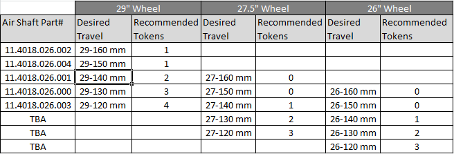
The air shafts have the specified travel marked on the bottom of the air shaft:

I have pretty much taken the instructions straight from the Pike manual (http://cdn.sram.com/cdn/farfuture/siWyhQzGiJhPG8iWT49C8QFszDSWdLtzC8TSQnymhtM/mtime:1385417915/sites/default/files/techdocs/gen_0000000004461_rev_a_2014_pike_service_manual_0.pdf)
However, I changed the order specifically to suit the task of reducing the travel. I have also included a few notes and tips, and I have added my photos of the procedure.
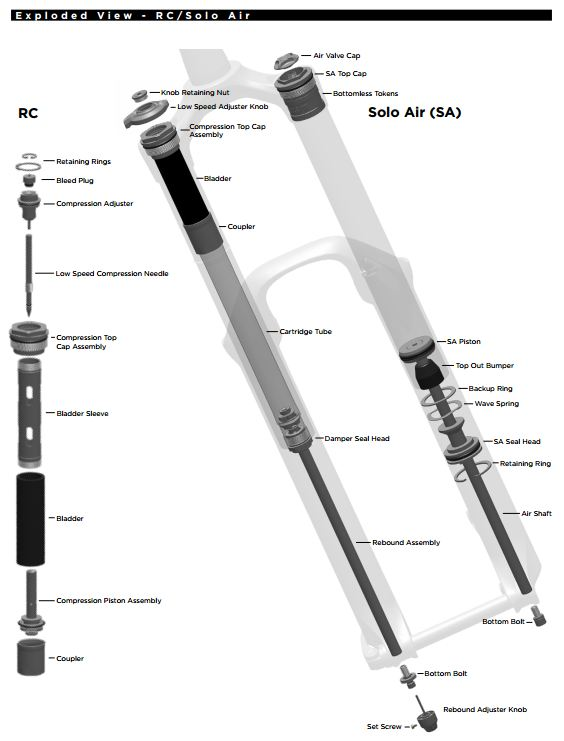
I will start off the procedure with an exploded view of the Pike RCT3 Solo Air which provides a better idea of what the air shaft assembly looks like (note the order of the Solo air piston, top out bumper, backup ring, wave spring, Solo Air seal head and rotating ring)...
Rockshox Parts needed:
- RockShox 0w-30 suspension oil
- Suspension specific grease (SRAM PM600 Military Grease, Rockshox Judy Butter, Buzzy’s Slick Honey)
- RockShox Pike Air Shaft (Solo Air) - See travel options below
- New crush washer (supplied in Pike Solo Air Full Service Kit or Basic Service Kit - I used a spare from my Revelation service kit)
Tools needed:
- Bike stand
- Rubber mallet
- Large screwdriver
- Small screwdriver
- Pick
- Large internal snap ring pliers
- Schrader valve core tool
- Long plastic or wooden dowel
- Clean, lint-free rags
- Isopropyl alcohol
- Shock pump
- Torque wrench
- Loctite Threadlocker Blue 242
- 2.5mm hex wrench
- 5mm hex wrench
Lower Leg Removal
- Remove the air valve cap from the top cap located on the non-drive side fork leg.

- Use a small hex wrench to depress the Schrader valve and release all of the air pressure from the air chamber. Use a Schrader valve core tool to remove the valve core from the valve body. Cycle the air shaft a few times to release the remaining trapped air.

- Use a 2.5mm hex wrench to loosen the set screw and remove the rebound adjuster knob located at the bottom of the drive side fork leg.

- Use a 5mm hex wrench to loosen both bottom bolts 3 to 4 turns

- Place an oil pan or bucket beneath the fork to catch the draining fluid

- Use a plastic mallet to firmly strike each bottom bolt to dislodge the air and damper shafts from the lower legs

- Use a 5mm hex wrench to remove the bottom bolt from the lower legs firmly pull the lower legs downward until fluid begins to drain. Continue pulling downward to remove the lower legs from the fork

Note: There is a noticeable difference in the sensation/sound when you tap the bolts with the mallet, you can actually feel the shafts dislodging. I found that I was able to slide the lowers down once I got the lowers past the 10% sag indicator. If the lower legs do not slide off of the upper tubes or if fluid doesn't drain from either side, the press fit of the shaft(s) to the lower legs may still be engaged. Reinstall the bottom bolts 2 to 3 turns and repeat step 6. - Leave the lowers in the bucket to continue to drain.

Solo air travel change adjustment
- Verify all air pressure was removed earlier during lower leg removal.
- Use a 24mm socket wrench to remove the top cap.

Note: I rounded my top cap slightly by using a standard 24mm socket, which has 1-2mm of a rounded edge before the actual traction so it doesn’t have the required traction for the thin top cap. There have been various recommendations to deal with this, the best suggestions being to either facing/machining a 24mm socket so it sits more flush, or to use a flat wrench (perhaps one specifically designed for this purpose e.g. Lunar bike tools - http://www.lunarbikes.com/tools.htm).
Side note illustrating the Lunar bike tools:
The Rockshox set comes with a 24mm wrench (for the air spring) a 30mm wrench (for the charger damper). The pictures below shows the tool profile, how it compares to a 24mm socket, and how well it fits on the Pike air spring top cap. Considering the fit of the Lunar 24mm wrench, I think I may still be okay using my lightly rounded top cap.


- Spray isopropyl alcohol on the upper tubes and clean the threads with a rag.

- Attach bottom-out tokens as required. These thread on to the bottom of the top cap.

- Place your finger over the end of the air spring shaft to prevent scratching the air shaft when removing the retaining ring.
Note: The retaining ring can pop off fairly quickly and could easily scratch the air shaft in the process. Scratches on the air shaft will allow air to bypass the seal head into the lower legs, resulting in reduced spring performance. - Use a small flat head screwdriver to push the Solo Air seal head tab under the retaining ring.Place the tips of large internal snap ring pliers into the eyelets of the retaining ring. Press firmly on the pliers to push the Solo Air seal head into the upper tube enough to compress and remove the retaining ring.

Note: This step is very tricky and it took some time to get the technique right with lifting the edge of the retaining ring with the screwdriver while using the snap ring pliers to release the retaining ring. This requires some careful handling and patience. (Apologies for not having any good pictures illustrating this). - Slide the retaining ring onto your finger and release the air spring shaft.
- Install the bottom bolt in the air shaft to pull the air shaft out of the upper tube.

- Firmly pull on the air shaft to remove the air shaft assembly from the upper tube.

- Clean and inspect the assembly for damage. Also note the order/position of the bumper cone, backup ring, new wave spring, and the Solo Air seal head.

- Spray isopropyl alcohol on the inside and outside of the upper tube. Wipe the outside of the upper tube with a clean rag.
- Wrap a rag around a long dowel and insert it into the upper tube to clean inside the upper tube.

- Remove the seal head, wave spring, backup ring and bumper cone from the air shaft, noting the order/position in which they are fitted on the old air shaft, as they will need to be installed in the same way on the new air shaft.
- On the seal head of the new replacement air shaft, use a pick or your fingers to remove the outer seal head o-ring and the air piston quad ring. I didn't bother with removing the inner o-ring and scraper because the inner o-rings are really tricky to remove without piercing them.

- Apply grease to the o-rings and scraper.

Note: For some reason greasing the o-rings isn’t mentioned in the Pike manual but this is something that I have always done on my Revelations and it says to do it in the Revelation 2014 manual. - Reinstall the o-rings on the seal head and the air piston.

- Install the bumper cone on the new air shaft with the broad base facing away from the Solo Air piston. Install the backup ring, new wave spring, and the Solo Air seal head (in that order) onto the air shaft. Tip: If you are not sure on the order or positioning, refer to the exploded view of the Solo Air Pike at the beginning of the Pike manual.

- Apply a liberal amount of grease to the air piston and seal head.
 Note: The manual says to use suspension specific grease which I presume they mean SRAM PM600 Military Grease. I used Phil Wood grease for this step.
- Firmly push the air shaft assembly into the bottom of the upper tube while gently rocking the air shaft side to side. Leave the seal head exposed.

- While the seal head is exposed, push the air shaft into the upper tube to prevent scratching when installing the retaining ring.
- Then push the seal head into the upper tube.

- Place the tips of large internal snap ring pliers into the eyelets of the retaining ring and install the retaining ring into the groove. The tab of the seal head should be positioned between the retaining ring eyelets.

- Install the bottom bolt in the air shaft to pull the air shaft out of the upper tube. Check that the retaining ring is properly seated in the retaining ring groove by using the snap ring pliers to rotate the retaining ring and seal head back and forth a few times. The retaining ring should click nicely into place on both side of the ring. Then firmly pull down on the air shaft.
Tip: Retaining rings have a sharper-edged side and a rounder-edged side. Installing retaining rings with the sharper-edged side facing the tool will allow for easier installation and removal. - Use a pick or your fingers to remove the top cap o-ring.

- Apply grease to the o-ring. Be careful not to apply any grease to the top cap threads.
- Insert the top cap into the top of the upper tube. The Pike manual says to use a torque wrench with a 24mm socket to tighten the top cap to 28 N·m (250 in-lb).

Note: As mentioned above, I rounded my top cap slightly by using a standard 24mm socket. There have been various recommendations to deal with this, the best suggestions being to either facing/machining a 24mm socket so it sits more flush, or to use a flat wrench (perhaps one specifically designed for this purpose e.g. Lunar bike tools - http://www.lunarbikes.com/tools.htm). The specified torque of 28 N·m is quite a lot of torque and using a torque wrench is probably not that necessary. In talking to a couple of bike mechanics, I have been told that with fork top caps you can pretty much just tighten them until they are tightly secure in place. So, meaning almost as tight as you can make it with a flat wrench but not putting all your weight into it (if that makes sense).
Lower leg foam ring oil bath
The lower leg seal service is not really required for this procedure. However, I will include the foam ring oil bath portion of the lower leg service since I have seen a certain amount of feedback saying that the foam rings were dry and that the original oil levels of the fork were low. So it is worth going through the leg seal service for the purpose of doing the foam oil bath (and re-greasing the dust wiper seals).
The lower leg seal service is not really required for this procedure. However, I will include the foam ring oil bath portion of the lower leg service since I have seen a certain amount of feedback saying that the foam rings were dry and that the original oil levels of the fork were low. So it is worth going through the leg seal service for the purpose of doing the foam oil bath (and re-greasing the dust wiper seals).
- Remove the wire springs from both dust wiper seals on both sides of the lower leg assembly.

- Place the tip of a large flat head screwdriver underneath the lower lip of the dust wiper seal.

- Stabilize the lower legs on a bench top or on the floor. Press down on the screwdriver handle to remove the dust wiper seal. Repeat on the other side
Note: Be very careful to keep the lower leg assembly stable and also not to apply too much force against the walls of the lowers as this damage the soft magnesium walls of the fork leg.
Tip: Here is good tip that I wish I followed for this procedure - put the screwdriver shaft and head in an old tube (to kind of wrap the screwdriver head). This will prevent the screwdriver head from scratching the inside of the lowers. - Wipe the old grease and oil off of the dust wiper seals.

- Inspect the internal wire springs in both dust wiper seals and check that neither of them were damaged in the process of removing the seals. If so then replace the damaged wire spring from the Pike basic maintenance kit.

- Use your fingers to remove the foam rings from inside the lower legs.

- In a small shallow tray, soak the foam rings in RockShox 0w-30 suspension fluid and let sit for the duration of the procedure.
Tip: The Park Tool Work Tray 106 has a small compartment that is perfect for this.
- Spray isopropyl alcohol on the inside and outside of the lower legs. Wipe the outside of the lower legs with a rag.
- Wrap a rag around a long dowel and insert it into each lower leg to clean the inside of the lower leg.

Lower leg assembly
- Reinstall the foam rings on the top bushings in the lower legs.

- If you have not already done so, remove the wire spring from the new dust wiper seal and set aside.
- Insert the narrow end of the dust wiper seal into the recessed end of the seal installation tool.

- Hold the lower legs steady and use the seal installation tool to push the dust wiper seal evenly into the lower legs until the seal surface is flush with the top of the lower leg surface.

Note: I noticed that the seals are capable of easily being pushed in too far, so be careful not to push the seals in too far. This is not something I have ever had happen with my Revelation. - Reinstall the wire spring onto the dust wiper seal.

- Repeat step 3 through 5 for the other side of the lower legs.
- Apply a liberal amount of grease to the inner surfaces of the dust wiper seals.

Note: The manual says to use suspension specific grease which I presume they mean SRAM PM600 Military Grease. I used Buzzy's Slick Honey for this procedure. - Slide the lower leg assembly onto the upper tube assembly just enough to engage the upper bushing with the upper tubes.Make sure both dust wiper seals slide onto the tubes without folding the outer lip of either seal or bending the wire springs. I found that the best way to do this is to wiggle the upper tubes gently into the wiper seals, one side at a time.

- Position the fork at a slight angle with the bottom bolt holes oriented upward. Angle the syringe fitting in each lower leg bolt hole so as not to fill the shaft. Inject 5 mL of RockShox 0w-30 suspension fluid into the drive side leg, and 15 mL of RockShox 0w-30 suspension fluid into the non-drive side leg.

Note: The Pike manual warns to not exceed the recommended fluid volume per leg as this can damage the fork. Tip: I found that getting the exact volume precisely right is tricky with the particular syringe I was using (the Stans No Tubes sealant syringe). I did a test run with water into a measuring jug to establish how to get the exact measurement. I then checked the amount of water in the measuring jug to confirm the correct volume of water. With my Stans syringe, to get exactly 15ml of suspension oil I had to fill the syringe just below the 15ml mark and then tap the tubing to make sure all the excess oil dripped out, so that there was only oil up to the nib of the syringe. Also, with the Stans syringe it helped to put the rubber plunger tip in the freezer for an hour or so, makes the plunger move easier.

- Slide the lower leg assembly along the upper tubes until it stops and the spring and damper shafts are visible through the lower leg bolt holes.

- Use a rag to wipe all excess fluid from the outer surface of the lower legs.
- Replace the crush washer on the bottom bolt of the air shaft
Note: Dirty or damaged crush washers can cause leaks. - Thread the bottom bolts into the corresponding shaft of each lower leg.


- Use a torque wrench with a 5mm hex bit socket to tighten the bolts to 7.3 N·m (65 in-lb).


- Install the rebound adjuster knob onto the rebound damper bottom bolt.

- Use a torque wrench with a 2.5 mm hex bit socket to tighten the set screw to 1.1 N·m (10 in-lb).


Note: Make sure to hold the rebound adjuster knob in place during installation to prevent damage to the bolt hole. - Refer to the air chart on the fork lower leg and pressurize the air spring to the appropriate pressure for your rider weight.

 Note: You may see a drop in the indicated air pressure on the pump gauge while filling the air spring; this is normal. Also, the lower leg assembly will jolt out as the pressure increases. Continue to fill the air spring to the recommended air pressure.
 - Thread the air valve cap onto the top cap of the non-drive side fork leg until it stops.

- Spray isopropyl alcohol on the entire fork and clean it with a rag
The results - axle-crown and travel measurements before and after
Before: the 27.5 Pike RCT3 at 160mm

Before: axle to crown measures 545mm (from the middle of the axle to the top of the crown)

After: the 27.5 Pike RCT3 at 140mm

After: axle to crown measures 535mm (from the middle of the axle to the top of the crown)

Only draw back is that you no longer get the full range of sag markings.
